Epoxy vs reinforced metal sleeve
In alignment with the ongoing pipeline integrity management system, the operator planned to excavate the location, remediate the identified defects and reinstate the crossing. Wood Group undertook repair design and repair options studies and recommended the use of epoxy sleeves.
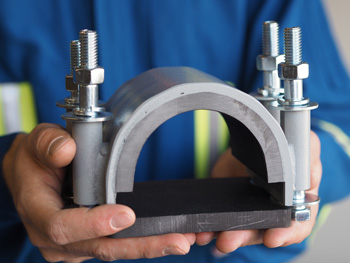
However, the operator’s engineering specifications stated that epoxy sleeves could not be used in areas subject to vibration, but that a Type-A sleeve (a tightfitting reinforced metal sleeve) was acceptable. Because of the anomalies on the outside of the pipe, it would have been difficult to fit a metal-on-metal sleeve, whereas the recommended sleeve has a gap between the metal components that is injected with epoxy to make the repair.
To justify the preferred repair strategy and conclude whether a deviation from the operator’s engineering specifications was applicable, Wood Group carried out vibration analyses of both the epoxy and the Type-A sleeves.
FEA models
In order to validate the proposed epoxy repair, Wood Group’s vibration specialists produced and compared finite element models of the epoxy and the Type-A sleeves. The models were 10 meters long and consisted of the pipeline, two 3-meter sleeves and one 2-meter sleeve. The three sleeves were spaced 10 millimeters apart to allow them to move independently (see Figure 1).
 |
|
Figure 1: Pipe, sleeves and epoxy layer |
Because the critical failure mode would be the tensile adhesion between the epoxy and the steel pipe, or the inter-laminar shear at the boundary, the models required through-thickness unaveraged stress distributions and were meshed with solid finite elements (instead of shell elements).
The models were analyzed to determine the natural frequencies and mode shapes. Figure 2 has the first mode at 33.5 Hz.
 |
|
Figure 2: Mode 1 for the epoxy repair |
Analysis method
There was no measured data available for the site, so an empirically calculated ground-borne velocity profile was used. Predicting the maximum vibration velocity level required taking into account the type of train, the distance from the track, the train speed, a ‘track quality’ factor and a building amplification factor.
 |
Where:
v = vibration velocity (mm/s RMS)
vT = empirically based value depending on type of train
D = distance from track (m)
D0 = reference distance (m)
B = empirically derived constant
S = train speed (km/hr)
S0 = reference train speed (km/hr)
FR = track quality factor
FB = building amplification factor
A conservative approach was taken, where a freight train traveling at 70 km/h passed over a pipeline buried 3.5 m below. This gave the following velocity amplitude profile (Figure 3):
 |
|
Figure 3: Velocity amplitude profile |
Measured vibration velocity spectra indicated that the typical frequency bandwidth for ground-borne vibration from passing trains was 2-200 Hz, so the profile was applied over that range to the two models.
Figure 4 is a typical stress plot showing the maximum value in the epoxy.
 |
|
Figure 4: Stress in the epoxy at 33.5 Hz when subjected to the velocity profile |
Figure 5 shows the response for the maximum nodal stress in the steel sleeve.
 |
|
Figure 5: Maximum stress response of a node in the steel sleeve |
All stresses for the maximum locations in each material were squared, summated and then square-rooted to give a root mean square (RMS) value. These were then multiplied by a crest factor of 5 (to give a quick idea of how much impacting is occurring in a waveform) and then doubled to provide a peak-to-peak (Pk-Pk) level.
Surprising results
Table 1 shows the results for the three critical locations across the two models.
| Epoxy Sleeve Stress (MPa) | Epoxy Stress (MPa) | Type-A Sleeve Stress (MPa) | |
|---|---|---|---|
| Pk-Pk | 18.442 | 1.064 | 21.342 |
The Type-A sleeve stress due to the vibrational loading was 21.342 MPa, which is higher than the 18.442 MPa stress found in the metal epoxy sleeve. Therefore, by the operator’s standards, the metal component of the epoxy sleeve is not considered to be an issue when subject to the magnitude of vibrational loading expected at this site.
For the epoxy sleeve repair, a stress of 1.064 MPa was calculated in the epoxy resin layer. For the resin in question, the limiting value would be the tensile adhesion between it and the steel. For this configuration, the value is 12.61 MPa. Therefore the calculated stress of just over 1 MPa has a large safety factor on the allowable tensile adhesion, especially due to the conservative assumptions used.
Larger compactor saves critical time
After the approval of the epoxy repair, the question was asked as to whether the model could be used to determine the groundwork equipment. As the railway line had to be closed for the work, and the window had to be kept to an absolute minimum, one of the main elements was the reinstatement of the site. This entailed compacting layers of backfill around, and then on top of, the repaired pipe. The larger the compactor, the thicker the layers; therefore the time it takes to complete can be reduced.
The excitation characteristics and footprints of the compactors were used in the epoxy model to show the stress levels for the operation, and on this basis, it was possible to use a larger compactor than originally suggested, saving critical downtime of the railway and pipeline.