Knowledge Center
- Downloads
- Technical Newsletter
- Recommended Guidelines and References
- Specifications
- Technical Papers
- Tools and Calculators
- Training
- Articles, Tips and Requirements
- An Integrated Approach to Manage Vibration Risks
- Design Requirements for Reciprocating Compressors
- Evaluating Compressor Operating Risks
- Five simple methods to check reciprocating compressor performance
- Important Differences in Pulsation Software
- Liquid Pumping Systems (Including Liquid Pipelines)
- Noise Regulations Around the World
- Noise Risks in the Gas Industry
- Performance Monitoring Examples
- Pipe Support Stiffness, GMRC Project
- Piping Vibration Design Considerations
- Piping Vibration Examples
- Structural Vibration and Ways to Avoid It
- Tips for a Successful Project (Vibration Control)
- Transient Conditions on Small-Bore Piping
- Vendor Requirements for Piping Vibration & Integrity Assessment
- Vibration-induced fatigue (whitepaper)
- Vibration Issues Affecting Gas Compressor Facilities
- Ask the expert
Pipe stress analysis – ask the expert
Q&A from our pipe stress analysis webinar "Stress relief"
The answers below were given in the context of the webinar and do not address all aspects of the issues discussed.
For more comprehensive information or application support, we strongly encourage you to contact us directly.
Contents [ hide ]
1 Videos
Videos shown in the webinar:
2 Analysis considerations and modelling techniques
a General
What is the purpose of the support spacing and nozzle load check?
A piping system with equipment nozzle connections should be modeled and reviewed so that loads, deflections and stresses due to weight, external displacements and forces, and changes in temperature and pressure are within the acceptable range of the material and equipment design.
 |
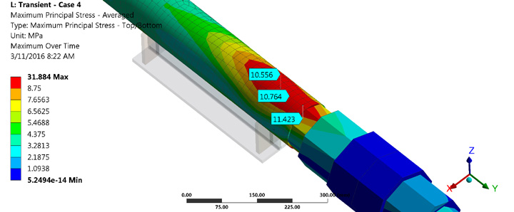
What benefits can FEA bring in addition to the nozzle loads discussed in this webinar?
FEA analysis generates stress results that are more sensible for industry applications. Use of FEA analysis can expand to a wide range of industry applications such as cylindrical junction, branch takeoff, nozzle loads, pad reinforced attachments, support design etc. One of the benefits is the economical advantage of eliminating unnecessary recommendations such as bend or special support thanks to more realistic stress results than conventional methods.
Is the maximum temperature 5 deg C or 5%? Should it be estimated as % from installation to max operating?
Maximum operating temperature plus 5 deg C or an additional 5% of the maximum operating temperature.
Should I check for friction sensitivity after the compressor and turbine line analysis?
Checking the sensitivity of friction is a good practice (if the project timeline allows).
Is it mandatory to model the compressor package and calculate nozzle loads? If we don’t have any vendor data, how would you approach the EPC scope of the piping?
It is difficult to say without more information, however, small-bore piping is particularly at risk for vibration-induced fatigue failure. Generally, solutions may involve bracing back to larger bore piping to prevent relative motion at the tubing connection, or strategically placed clamps to limit mechanical resonance in the tubing. If you would like more information or assistance with your project, please contact our vibration, dynamics and noise team.
b Stress analysis
 |
Which nozzle loads should I give to the vendor of a reciprocating compressor when the piping stress model boundary is a scrubber or vessel?
Scrubber and vessel nozzle loads connecting the piping.
Can vibration data (coherence, cross power spectrum, FRF, etc) be used for modeling piping stress?
Yes, vibration data can help determine the risk of vibration failure.
What is the basis for not considering steam-out in the flexibility analysis?
For a typical piping flexibility analysis, we only consider low-cycle fatigue (7,000 cycle). Unless steam-out conditions occur at 7,000 cycles, they should be analysed as part of considerations outside of the piping flexibility analysis.
Will there be pipe growth in short run pipes and temp of <150C
Yes, there will be thermal growth.
What is the reference of stress vs cycle numbers graph?
Stress Range Factor, f can be found in Fig. 302.3.5 of B31.3
Can dynamic strain measurements be used to determine existing piping stress?
Yes, measuring strain can determine the stress level.
c Vibration/dynamic analysis
i General
Should I consider vibration velocity at higher harmonics?
Yes, because vibration at higher orders can cause fatigue failure, especially on small-bore piping.
Apart from stiffness, have you ever used support friction and damping to reduce vibration?
During the design stage, playing with damping might be ideal case. However, applying damping to the system by adding damping material or others can be a very effective way to reduce piping vibration when options are limited.
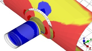
Please elaborate more on acoustical length of piping
|
|
| Certain pipe lengths can significantly increase pulsation |
Watch our webinarFeeling the pulse for more information on acoustical pipe lengths. We're also working on a new pipe-lengths-to-avoid calculator that we'll publish on our website.
How to consider dynamic reactions in thermal flexibility analysis?
A thermal flexibility analysis typically only considers static loads. For systems experiencing dynamic loads (vibration), an additional, dynamic analysis is required to prevent high-cycle fatigue failures.
When using vibration analysis to determine vibration effects, do you use displacement velocity or acceleration? Which is better, ODS or modal analysis to determine nodal points?
Depending on the frequency of the vibration, we use all type of sensors
Would the same analysis techniques be used for subsea piping?
Conditions for piping might be different, but depending on the forcing frequency, the approach to resolve piping vibration should be the same.
Learn more about subsea piping vibration
Do you review the dynamic susceptibility and piping natural frequencies from stress analysis software as a preliminary indication that vibration could be a concern?
Preliminary indications of vibration concerns are: rotating machinery speed, size of pipe, and support spans. The piping natural frequency can be determined in more detail through FE analysis.
In regions with high seismic forces, like Chile, seems seismic analysis is the govern limitation in design. And vibration is just a verification in most cases. Do you agree? What is your experience with that?
Criteria for seismic analysis compliance and vibration compliance are different. Both need to be addressed individually for any system under vibration and seismic concerns.
How do you approach vibration issues on furnace outlet piping where the source of vibration is caused by two-phase flows and other non-rotating equipment issues.
 |
| The magnitude of a slug load is proportional to the pipe size, slug speed and density |
Two-phase flow-induced loads are to be calculated and applied to all locations of pipe change in direction and ensure that the loadings on the elbows, nozzles, anchors etc. are within allowable levels.
What methods do you suggest for reducing slug-induced loads and vibrations?
The magnitude of a slug load is proportional to the pipe size, slug speed and density. Reducing any of the three parameters will reduce the magnitude of the load itself. To reduce the effects of vibration, a suitable type of restraint to be placed at areas where displacement are expected due to slug loads.
Do we need to analyse a slug flow system for vibration, or just add guides at certain intervals?
A slug analysis can also determine the reaction forces at the support. The location of support is important. In addition, check if the support can hold the force generated by the slug.
Learn more about multi-phase and slug flow
ii MNF
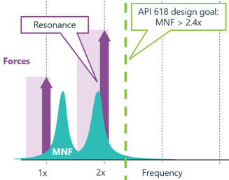 |
| API 618 design goal: MNF must be greater than 2.4x compressor operating speed |
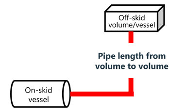
When designing piping to an MNF of 2.4x operating speed of equipment, how far away from the package does this higher MNF requirement apply?
Depending on the level of pulsation, a typical approach is to model up to the next volume, where pulsation diminishes effectively.
How do you determine the mechanical natural frequency of a piping system?
The natural frequency depends on the number and location of supports, pipe size, layout, schedule, etc. Due to the complexity of piping designs, it is better to calculate the natural frequency with a finite element analysis.
Do you normally calculate the acoustical natural frequency of the piping system in your pulsation analysis?
Absolutely. We analyze the entire intended operational speed range and compressor configurations to determine possible acoustic resonances. It is these resonances that we design around to keep pulsations and resulting shaking forces within guidelines.
When analysing piping systems local to a vibration source, is there a rule of thumb for how far from the source you should consider? Eg, at what point does the natural frequency no longer become a concern?
Pulsation waves travel from the source not only in the fluid flow directions but also in the opposite direction. The resultant vibration tends to diminish through multiple passes (ie, cooler), larger volume (tanks) etc.
What to do if the piping frequency is less than the compressor frequency due to layout limitations?
Adding more supports to raise the MNF could be a simple fix. If that is not practical, consider a more sophisticated method such as a forced response analysis to calculate stress and vibration levels.
Would it ever be appropriate to design the MNF to be less than the forcing vibration frequency (eg, car engine mounts)?
Yes, it is also ideal to design the MNF below the forcing frequency. A typical example would be foundation analysis. A typical machinery foundation has an MNF below forcing frequency.
iii Stiffness
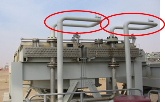 |
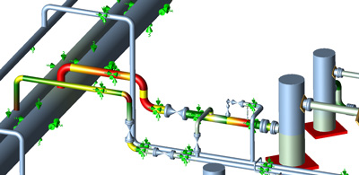
| Pipe loops like these create a high vibration failure risk |
What is the best way to stiffen a pipe that has resonant vibration?
If the vibration is due to a bending mode, adding more pipe clamps would be an easy way to resolve the problem. Make sure the supporting structure also provides enough stiffness to the clamp.
How do you determine cylinder stiffnesses?
Cylinder stiffnesses can be determined via FEA analysis
In some cases, it is not possible to have support stiffness as per API requirements, in those cases what is the best way to do the analysis?
If support stiffness per API requirement cannot be met, then the shaking force level needs to be minimized.
How do you calculate support stiffness of supports on pipe racks?
We recommend using the minimum stiffness provided in API 618 as a starting value for the analysis.
Can you comment on the use of nozzle stiffness in the stress study?
A typical analysis of an equipment nozzle models the connection to be rigid for a more simplified process. Nozzle stiffness can be calculated via FEA and applied to the stress model to reflect more realistic reaction loadings.
d Software
What software do you use for flexibility and dynamic analysis or both?
We use an in-house developed software for dynamic analysis (MAPAK), in combination with ANSYS. We mainly use Caesar II for flexibility analysis.
What finite element software do you recommend for modelling pipework?
ANSYS, Solidworks Simulation and FE Pipe (PRG) are typically used by industry.
3 Pipe supports
How do the flexibility and dynamic analyses make a difference in the pipe support design?
As presented in the webinar, these two analyses have contradicting solution strategies. A flexibility analysis seeks to allow piping to grow and reduce the number of supports; a dynamic analysis seeks to restrain piping and add supports. The solution that can satisfy both of these requirements may require a combination of different support types and locations, so it is important to consider both analyses.
.jpg) |
| U-bolts are NOT suitable to restrain vibrating piping |
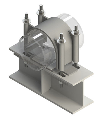 |
| ThermaGlide™ anti-vibration clamps can control vibration while allowing thermal growth |
Should I use spring washers on clamp bolts?
Spring washers can help prevent over-torque during the installation but they are not necessarily required.
Can thermal type supports (guide and rest type) constrain dynamic vibration?
Guide and rest type supports cannot constraint vibrating piping.
Can supports with a lateral gap (for thermal expansion) constrain piping from dynamic loads?
Generally, a typical thermal type supports with gaps cannot constrain piping dynamically. However, ThermaGlide anti-vibration clamps can both allow thermal growth while controlling dynamic movement.
Do you recommend against using u-bolt style clamps?
We do NOT recommend u-bolts for vibration applications.
How do you constrain degrees of freedom for supports considering thermal loads at guide and rest type supports.
- Rest support: add +Y restraint with 0 gap
- Guide: add +Y restraint with 0 gap and ± lateral restraint with gap of 1/16
How to specify the degrees of freedom for anti-vibration clamp in Caesar II?
Specifying the degrees of freedom for anti-vibration clamp is not required.
How to model A-Frame support for pulsation vessel in stress analysis?
For the piping flexibility analysis, a pulsation vessel is the boundary condition. Including an A-frame support in the model increases the accuracy. Make sure to consider the stiffness at the shell and the stiffness of support structure in the analysis.
Is a sustained load adequate to restrain vibration?
No, a sustained load is generally not adequate to restrain vibration without restraints. Vibration can happen in directions other than -Y.
Is there any support type recommendations for surge analysis piping?
Support type recommendations will be the same for piping subject to surges as for typical vibratory services. That is, supports that provide enough stiffness to ensure a vibratory node (pipe will not move) at the support. Wood recommends hold-down type supports as u-bolt type supports tend to wear into the pipe.
Are shoes useful in vibration service? I remember from in the EI guidelines that you can consider the spacing between shoes when evaluating the unsupported length for the flow-induced vibration calculation.
Correct; shoes can be useful in vibration services if used in the correct locations.
Around areas of high vibration, near equipment, or changes in direction, shoes will not dynamically restrain the piping and it is better to use hold-down type clamps.
However, in long straight runs of piping such as headers, in areas away from elbows the piping is unlikely to experience significant shaking forces (as there is little area for a pulsation to act upon). In these cases, shoes may be sufficient.
Can you ensure bolt torque applied to clamp supports remains throughout the life of the support given it is subject to vibration?
We found that bolts need to be check regularly for vibratory loosening.
Clamp stiffness for analysis – only in axial direction or also transverse? And if transverse is applicable, how it is modelled/approximated properly?
Typical pipe clamps have both axial and transverse stiffnesses.
In case you use anti-vibration clamps with some gaps, how you model support in Caesar for calculating natural frequency?
Caesar software cannot determine the natural frequency of the system accurately due to a limited modeling method of boundary conditions. Pipe clamps in Caesar can be modeled by considering hold-down clamping action.
4 Measurement
Can dynamic strain measurements be used to determine existing piping stress?
Yes, measuring strain can determine the stress level.
Do you collect MNF in all three axes on the piping?
Yes, we collect MNF in all directions.
How do you measure and manage in-plane (shell) vibration?
Pipe shell modes can be measured with a multichannel measurement device. Measuring shell vibration requires at least eight sensors around piping circumferential excitations.
5 Other
Is this topic applicable to water supply piping conditions?
Yes, this topic is applicable to any piping subject to a vibratory service. Wood studies pump systems with a similar methodology.
Could you explain how bottles are supported? Should this information be provided by the equipment vendor?
Typically, bottles are supported by the cylinder. Ideally, the vendor would provide the information, however, this can be difficult to obtain within the project schedule. Therefore, calculating it is often the more realistic approach.
What office are you guys working at? What region do you both cover?
We have vibration, dynamics and noise offices in the US, Canada, the Middle East, SE Asia, Australia and the UK. The presenters of this webinar are based in Calgary, Canada, working for customers and projects around the world.
More questions?
Don't hesitate to contact our pipe stress and vibration team.
6 Online calculators
Maximum recommended support spacing – support spacing and stiffness for vibratory service
API 618 guideline calculator – how does this industry standard apply to your compressor?
Helmholtz calculator – how effective will your bottle be at reducing acoustical pulsations?
Online bottle sizing – sizing recommendations for pulsation bottles used on reciprocating compressors
Pipe lengths to avoid calculator – calculate how to avoid resonant pipe lenghts in yor system
7 More webinars
Related Pages
Webinar: Stress relief • Pipe Stress Analysis • Webinar: Shake, rattle and grow I (2022 update) • Pipe stress modelling techniques – ask the expert •
Free webinar

Learn how to solve complex vibration problems with advanced troubleshooting techniques to keep your facility running smoothly, with minimal downtime. Watch now
