Knowledge Center
- Downloads
- Technical Newsletter
- Recommended Guidelines and References
- Specifications
- Technical Papers
- Tools and Calculators
- Training
- Articles, Tips and Requirements
- An Integrated Approach to Manage Vibration Risks
- Design Requirements for Reciprocating Compressors
- Evaluating Compressor Operating Risks
- Five simple methods to check reciprocating compressor performance
- Important Differences in Pulsation Software
- Liquid Pumping Systems (Including Liquid Pipelines)
- Noise Regulations Around the World
- Noise Risks in the Gas Industry
- Performance Monitoring Examples
- Pipe Support Stiffness, GMRC Project
- Piping Vibration Design Considerations
- Piping Vibration Examples
- Structural Vibration and Ways to Avoid It
- Tips for a Successful Project (Vibration Control)
- Transient Conditions on Small-Bore Piping
- Vendor Requirements for Piping Vibration & Integrity Assessment
- Vibration-induced fatigue (whitepaper)
- Vibration Issues Affecting Gas Compressor Facilities
- Ask the expert
Piping Vibration Examples
These examples illustrate various piping vibration problems. Advanced vibration analysis is required to solve these dynamic issues: flow-induced vibration (FIV), acoustic-induced vibration (AIV), and other common issues. Wood recommends that piping vibration be assessed during the design stage to avoid costly piping modifications during operations. See Piping Vibration and Integrity Assessment
Contents [ hide ]
1 Video: examples of piping vibration
2 Hydrogen/Butane Gas Compressors (FIV Example)
This refinery utilizes large centrifugal compressors. The piping system is shown below (left). Vibration problems occurred on the piping header feeding three dryers (right).
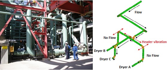
Normally the gas flow travels through two dryers and no vibration issues occur but under regeneration, the operators use only one dryer. When flowing to one dryer, the operator measured high vibrations in the header as shown by the red arrows (above, right).
Wood’s field team was hired to analyze and address the problem. While onsite, Wood measured natural frequencies, vibration displacement, pressure pulsations, operating deflection shape, and other parameters. After reviewing the results it was confirmed that the vibration was due to a complex FIV problem. Note that FIV can also be called Eddy Shedding or Vortex Shedding.
One solution was to eliminate flow-induced excitations by changing the length of the inlet header and the distance between Dryer A and B inlet valves. This was determined to be too expensive, so Wood designed supports to be installed at specific locations in order to shift the mechanical natural frequency away from resonance.
Evaluating FIV risks during the design stage is recommended for centrifugal compressor systems, and will avoid expensive piping modifications during operations.
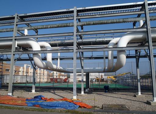
3 Turboexpander/Booster Compressor (FIV Example)
For this deep cut gas plant, the process removes ethane and propane from the natural gas stream. To save energy, a turboexpander is used instead of an inefficient, and therefore costly, Joule-Thompson Valve.
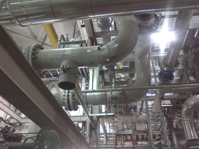
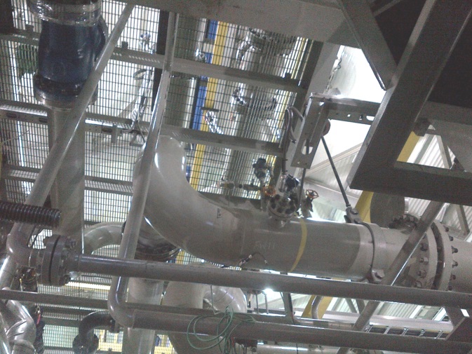
Wood was hired to address severe vibration in the overhead suction piping system. The vibrations were so severe that personnel did not want to be present in the building for fear of piping failure. As seen in the pictures below, the piping system is complex with many dead legs.
 |
 |
Wood measured high pulsations in the suction dead legs at 15 Hz, the same frequency as the calculated Strouhal frequency. This confirms the excitation force was due to the 15 Hz pulsations and is an FIV problem.
The standard FIV problem occurs when a quarter wave Acoustical Natural Frequency (ANF) coincides with the excitation frequency (15 Hz pulsations); but in this case, the problem was much more complicated than the standard FIV problem. All of the relevant dead legs were analyzed and it was discovered that none of them matched the 15 Hz frequency (quarter wave ANF).
So what explains the piping resonance and severe vibration?
After reviewing the piping geometry in more detail, Wood discovered that an entire piping section comprising of the header and dead legs had a 15 Hz ANF – something very rarely seen. Once the source of the FIV problem was found, Wood recommended modifications to alleviate the resonance.
This example illustrates that evaluating ANFs can be complicated, requiring specialized acoustical analysis software and analysis techniques. Wood’s software tools provide a cost-effective approach to identify and avoid these risks during the design stage.
4 FIV and AIV Analysis for Centrifugal Compressors
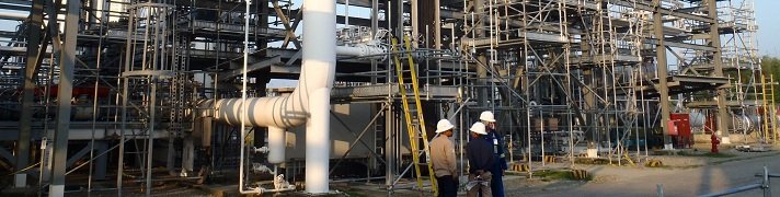
Wood was retained to assess piping vibration in a large centrifugal compressor facility used for power generation. Higher vibrations were measured when the compressor’s recycle valve was 40% open compared to when it was only 23% open.
The following schematic shows the main piping system including hot and cold recycle. The area of high vibration is shown by the dotted circle. Wood’s engineering design team identified many locations where FIV or AIV could be the source of the excitation forces.
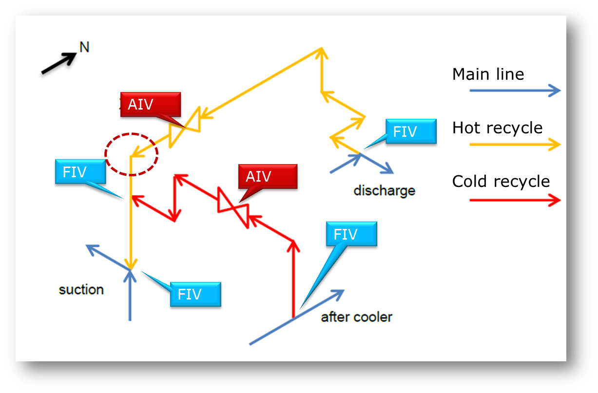
Each of the potential FIV and AIV locations were evaluated in more detail including different operating scenarios (flows, temperatures, etc.). Through this advanced analysis, Wood was able to identify one FIV location and one AIV that likely contributed to the problem.
Recommendations to modify the valve trim will reduce the risk of AIV problems. To reduce FIV problems, certain flow rates should be avoided. This is not always practical, therefore, other solutions were provided. This case illustrates the combination of FIV and AIV risks that affect piping systems.
5 Piping Vibration on Sales Gas Line (Gas Plant Example)
 |
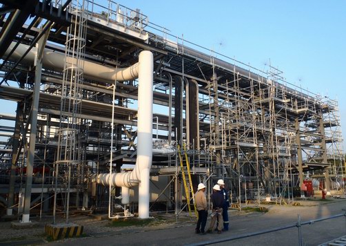 |
The 30 inch (75 cm) sales gas line had high vibration at this Asian Gas Plant. High vibration became evident on the main sales gas line under high flow / high pressure drop conditions following the installation of a new whisper trim pressure control valve. Wood’s staff conducted a site vibration assessment to determine the cause of and possible solutions to piping vibration and integrity concerns.
Based on the field analysis, the vibration upstream of the control valve is caused by Flow-Induced Excitation (FIE, also called FIV) which is created when gas flows past a dead leg. The dead leg creates vortices, which are amplified by the standing wave in the dead leg. These pulsations travel through the pipe and cause it to shake.
Three solutions were identified to reduce the excitation forces. These options included: modifications to the operation of the bypass valve; a minor modification at the mouth of the dead leg; or modifying the piping geometry by moving the recycle valve.
Under some flow condition the piping at the expansion loops was observed to exhibit very high vibration. The piping in this area is very loosely supported and any unbalanced force in the piping system will result in high vibration on these lines. If the FIV created by the dead leg near the control valve cannot be controlled, then increasing the stiffness of the expansion loops will help control vibrations. Wood provided recommendations on adding beams to support the elbows. In addition to these piping support recommendations, a pipe stress analysis is required to ensure the additional supports do not create thermal stress problems.
Related Pages
Webinar: Small bore…Big problem • An Integrated Approach to Manage Vibration Risks • Pipe Support Stiffness, GMRC Project • Piping Vibration Design Considerations • Tips for Managing a Successful Vibration Project • Transient Conditions on Small-Bore Piping • Webinar: Shake, rattle and grow I (2022 update) • Webinar: Shake, rattle and grow – part II •
Free webinar

Learn how to solve complex vibration problems with advanced troubleshooting techniques to keep your facility running smoothly, with minimal downtime. Watch now
