Services
- Static Equipment & Structures (Piping Vibration & Fatigue)
- Acoustic Fatigue Assessment for Blowdown Systems
- Acoustic-Induced Vibration (AIV) Analysis
- Finite Element Analysis (FEA) and Computational Fluid Dynamics (CFD)
- Flow-Induced Turbulence (FIT) Analysis
- Flow-Induced Vibration (FIV) Analysis
- Multiphase and Slug Flow Analysis
- Pipe Stress Analysis
- Piping Vibration and Integrity Assessment
- Review & Design Support Services
- Small-Bore Connections (SBC) Assessment
- Structural Vibration and Dynamic Design Analysis
- Subsea Piping Vibration
- Thermal Striping
- Tube Failure Analysis
- Veridian AM
- Veridian VS
- Vibration Inspection Program
- Water Hammer Analysis
- Machinery Analysis
- Bottle Sizing Service
- Compressor Package Engineering
- Finite Element Analysis (FEA) and Computational Fluid Dynamics (CFD)
- Foundation Design and Dynamic Analysis
- Fuel Gas Compressor Piping Transient Analysis
- Lateral Vibration Analysis
- Pipe Stress Analysis
- Pulsation & Mechanical Analysis: Reciprocating Compressor
- Pulsation & Mechanical Analysis: Reciprocating Pump
- Pulsation & Mechanical Analysis: Screw Compressor
- Pump RCF Analysis
- Review & Design Support Services
- Shell Transverse Acoustical (STA) Analysis
- Skid Design and Analysis
- Surge Control Design for Centrifugal Compressor Systems
- Torsional Vibration Analysis (TVA)
- Field Engineering & Troubleshooting
- Finite Element Analysis (FEA) and Computational Fluid Dynamics (CFD)
- Human Vibration
- Motion Amplification Vibration Analysis
- Noise Troubleshooting
- Performance Assessment (Thermodynamic)
- PostPro – field data processing and analysis
- Structural Vibration Troubleshooting
- Thermal Striping
- Troubleshooting, Root Cause Analysis (RCA)
- Veridian iDAC
- Vibration Inspection Program
Multiphase and Slug Flow Analysis
Impact on fatigue and dynamic stress in piping systems
 |
| Stress concentration around a pipe support due to unsteady multiphase flow |
Multiphase flow occurs when different fluid phases are mixed and flow in the same pipe. Depending on the phase velocities and densities and the ratio of liquid to gas, different flow regimes might exist - for example stratified, slug or annular flow. Although slug flow is often considered to be the most problematic from a vibration perspective, recent experience has shown that other flow regimes can give rise to significant piping vibration.
In the oil and gas industry multiphase flow is often encountered, and if not taken into account during the design of a process system can lead to excessive vibration, resulting in unreliable operation and eventually fatigue failure.
Contents [ hide ]
1 Why is multiphase flow an issue?
The risks from flow- or process-induced vibration excitation of pipework are widely acknowledged in onshore process plants, offshore topsides and subsea facilities. Multiphase flow is particularly of concern because forces can vary considerably with flow regimes, and so relatively small changes in the gas to oil ratio can result in significant changes in dynamic force levels. These forces can be relatively broadband in nature and can therefore excite a range of structural modes.
A stress or fatigue study should be considered when:
- Flow rates are increased or changes to the gas to oil ratio are considered
- Thermophysical properties of transported fluids are changed
- Hydrodynamic- or terrain-induced slugging is possible
2 Design
A multiphase flow study starts with a detailed CFD analysis to predict the time-varying velocities, forces and pressure levels in the piping system. These forces are then applied on a structural model of the piping system to predict vibration and dynamic stress levels, which can then be compared with acceptance criteria to assess the severity of the flow conditions and predict the fatigue life of the system.
During the project design stage, we can support the project team through carrying out a range of high-end engineering services:
- Force predictions to identify the amplitude and frequency content of the flow-induced forces
- Mechanical natural frequencies (MNF) calculations to assess the risk of vibration modes to be resonant
- Guidance on optimal support locations to minimize thermal stresses and avoid resonance
- Detailed simulation to identify the maximum vibration levels and dynamic stress amplitudes and how these vary with operating condition
3 Case Study
An operator recently contacted Wood to investigate whether they could increase the flow rate in an existing 4” (100 mm) pipe connecting a Christmas tree to a production header.
 |
|
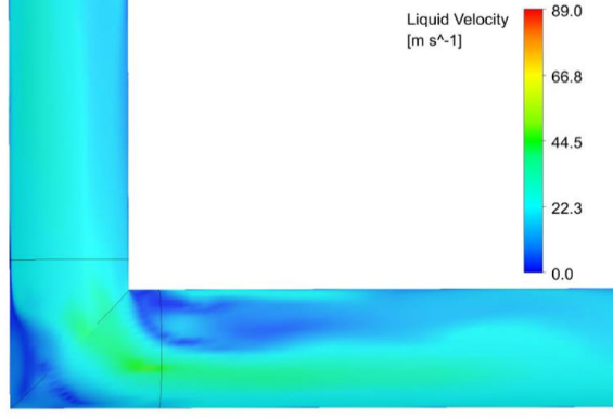
Figure 1: Liquid velocity at the midplane of an elbow |
The pipe was only supported at two locations and important thermal distortions were predicted to change the support conditions during operation. The operator was worried that the new flow conditions would result in slug flow.
First, Wood modelled the flow in the pipe and predicted the velocity distribution. This is illustrated Figure 1 which shows a typical liquid-velocity variation at the midplane of an elbow. High-velocity bands are observed as the flow travels around the elbow. The CFD model was then used to also predict pressure levels and calculate the time variation of forces generated in each direction and at different elbows (Figure 2).
The results showed a rapid variation of forces, along with fairly different force levels at each elbow due to the multiphase flow characteristics being modified as the flow progressed from bend to bend.
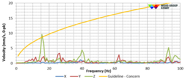
These forces were then applied to an FEA structural model to predict the transient response of the pipe. The Fast-Fourier Transform (FFT) of the vibration signals at key elbow locations were calculated and compared to the EI guideline vibration velocity limits (Figure 3). The results predicted the dominant response to be at 15, 40 and 85 Hz.
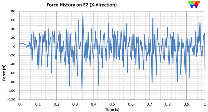 |
| Figure 2: Time history corresponding to the horizontal force at one of the elbows |
 |
|
Figure 3: Vibration levels at elbow location compared to the Energy Institute (EI) Guideline |
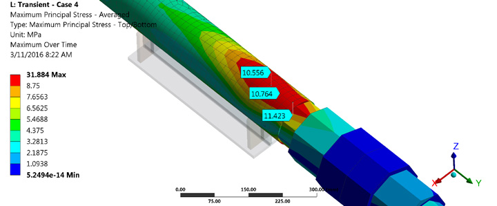 |
| Figure 4: Stress levels around a shoe support |
4 Research and joint industry projects (JIPs)
 |
 |
| SLARP JIP testing setup and FEA model |
Wood is managing a SLARP JIP, which deals with the development of methods for the design and analysis of slug loading and response in subsea pipelines, risers, jumpers and free-spans.
The JIP is structured around three key aspects:
- Development of global numerical analysis models for the prediction of pipeline and riser structural dynamic response to slug flow
- Full-scale model testing and global finite element analysis correlation
- Development of an industry design guideline reflecting best practice design and analysis techniques for determining structural response to slug flow
Phase 3 was formally kicked-off in November 2014 with plans to expand the testing and numerical validation that was completed as part of Phase 2 and provide enhanced knowledge, understanding and value to the development of the JIP design guidelines and analytical methods. Participants for Phase 3 include BP, Chevron, Total and Saipem.
4 Inquiries
Wood’s vibration, dynamics and noise (VDN) group has been involved in joint-industry projects (JIPs) for several years to understand and determine multiphase flow characteristics and the associated dynamic response of piping systems. Our group of experts provides a comprehensive analysis strategy for such flow conditions. The strategy is based on sophisticated simulation tools backed by experimental data.
For more details, or to discuss your specific multiphase flow concerns, please email our dedicated CFD and FEA experts at info.vdn@woodplc.com.
Related services
- Piping Vibration and Integrity Assessment(Energy Institute Study, 2008, AVIFF)
- Pipe Stress Analysis
- Flow-Induced Turbulence (FIT) Analysis
- Flow-Induced Vibration (FIV) Analysis
Keywords
- Multiphase Flow
- Slug flow
- Piping vibration
- Pipeline
- Flow-induced vibration of piping and pipelines
- CFD
- FEA
5 CFD examples
|
|
|
|
Free webinar

Learn how to solve complex vibration problems with advanced troubleshooting techniques to keep your facility running smoothly, with minimal downtime. Watch now